Inhaltsverzeichnis
Morse Code Callsign Loop
When establishing RF communications, in particular in a portable setting, an automated CW callsign loop can be a handy capability of any transverter. Since this issue has repeatedly come up, a quick design was whipped up to satisfy this demand.
Design
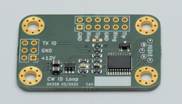
The design is extremely simple: A small PCB is connected to the CW input of any chosen transceiver. A tiny on-board MSP430 CPU monitors a front-panel switch and automatically keys the transceiver by repeating a programmable text.
The design is available publicly in KiCAD format here: https://git.loetlabor-jena.de/thasti/cwloop
Software
The MSP430F1111A software is open source and included in the Gitlab Repository. The transmission text can be modified in the source code.
For building, an installation of `mspgcc` is required. Additionally, `msp430-bsl` from https://pypi.org/project/python-msp430-tools/ can be used for programming, a Makefile is included. The wiring described on the MSP430dev page is applicable for programming.
Hardware
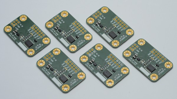
6 PCBs were assembled on 19.03.2022 and software was tested. Power consumption is around 1 mA (mostly consumed by the bright red LED power indicator). The LDO offers reverse polarity protection, which was confirmed to work properly. The design is considered working and may be reproduced if desired. For fabrication at AISLER, the following project was used: https://aisler.net/p/YIPXJVDW
Complete mini production lot after testing:
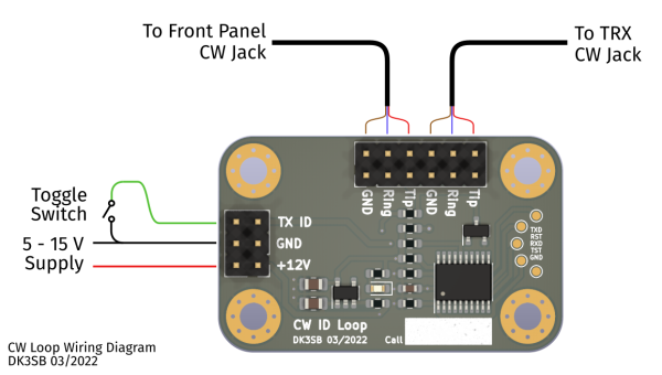
The PCB can be wired as shown below: A front panel toggle switch is used to enable/disable the CW generation, and two audio jacks can be wired to the front panel and the transceiver. This allows using a manual/paddle keyer in addition to this circuit. The PCB simply pulls the „tip“ contact to ground to key the TRX.


