Inhaltsverzeichnis
Compact 10 GHz transverter
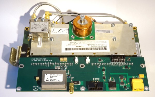
There are 10 GHz transceiver modules from Cambridge Broadband Networks available at eBay. Based on these modules a compact transverter(in contrast to former modular approaches) for the 3 cm amateur radio band was built.
schematics: 10g_cambridge.pdf
project files: 10g_cambridge
First all the details of the modules were reverse engineered(documented here in german) and a concept for the usage as a 3cm transverter was worked out.
Concept
The idea is to use as much as possible parts from the original design and adapt them to a simplex transverter with the same IF for receiving and transmitting.
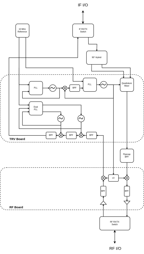
As transceiver IF 50 MHz is used. The transmit path is designed for <1W input power. With a 90° hybrid coupler the quadrature mixer in the transmit section of the transceiver module is used as a image reject mixer to 2.63 GHz. This IF gets filtered externally with a 28mm pipe cap filter to further attenuate the LO and side-band signal (+harmonics). In the first built 0.5 W output power could be reached without additional tuning of the power amplifier. The receiving chain consists of 3 translations from 10 GHz to 2886 MHz to 320 MHz to 50 MHz. There is very much gain involved and can be adjusted by several step attenuators. On the first built the noise was adjusted to be 10 dB higher than the noise of the transceiver to maintain a good noise figure. Switching between receiving and transmitting needs reprogramming of the synthesizers and switching of RF and IF, which is handled by the MCU. An integrated 10 MHz OCXO delivers reference signals for all the PLL synthesizers.
Modifications
Transverter PCB
The transverter PCB is visible on the top of the unit. To perform the modifications shown below, its milled RF shield needs to be removed. For this, only the screws visible on top of the RF shield need to be removed, the PCB itself can remain screwed to the base of the unit.
TX Baseband Filters
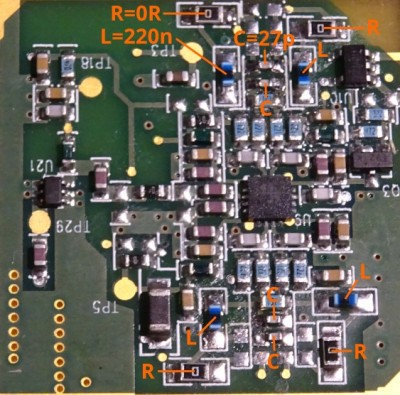
The original lowpass has a cutoff frequency of ~12 MHz, which is replaced by a 3rd order 60 MHz filter. From each filter (I and Q, respectively), unsolder four inductors and five capacitors. Replace with components as shown on the picture below.
RX IF Filter
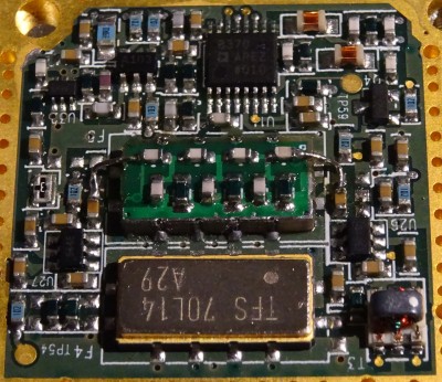
The original 70 MHz IF filter is not used and the signal path is switched to the second not populated filter footprint. A pcb with a 3rd order 50 MHz bandpass filter was made and fits on this footprint.
schematics: RX IF filter
project files: if_cambridge
errata:
- PCB pinout is flipped vertically, hence short wires are required to connect RF path to coupling capacitors on the PCB.
TX IF Filter
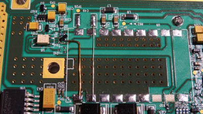
The original ceramic filter is removed and the attenuators are replaced by 0R resistors. The green inductor at the far end of the line remains in place. Since it provides a low resistance path to ground prohibiting probing for shorts, careful optical inspection of the modification is useful.
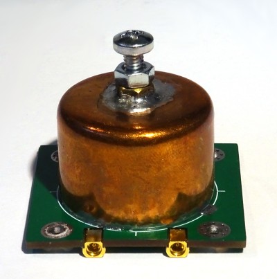
In theory image rejection by the quadrature mixer can be tuned to -60 dBc or better, however thermal drift limits the image rejection to about -50 dBc. A pipecap filter (constructed from a 28 mm pipecap) is therefore inserted between the transverter board and the RF board. It connects in-line using the external MCX connectors.
project files: if2_cambridge
errata:
- MMCX instead of MCX used, fix in next revision
RF Board
The RF board is the lower, large PCB enclosed between the two main halves of the body. The RF board is exposed simply by removing the six large screws on the bottom of the unit. The thermal/electrically conductive pad on the bottom might obscure these screws and needs to be removed.

