Inhaltsverzeichnis
10 GHz Frequency Multiplier for the Amateur Laboratory
Acquiring signal generation capabilities for laboratory use in the 10 GHz frequency range can be difficult and expensive. Old lab instruments are typically not stable while newer equipment tends to be very pricey. Often, a lower frequency source can be more cheaply acquired and then be converted to the 10 GHz range using a multiplier.
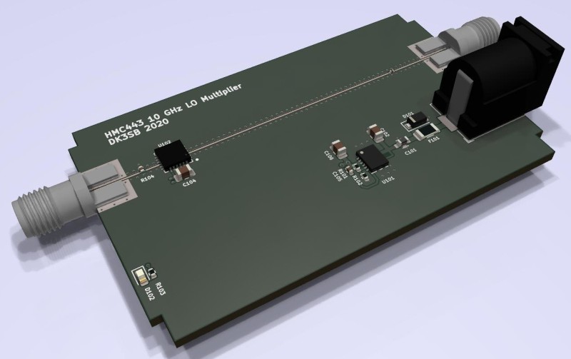
This simple PCB hosts an Analog Devices HMC443 multipy-by-four RFIC, whose frequency range covers the LO, output and image frequencies of typical 10 GHz narrowband transverter architectures. It can produce up to +5 dBm of output power, while power and output return loss can be traded off by means of an SMD attenuator assembly option.
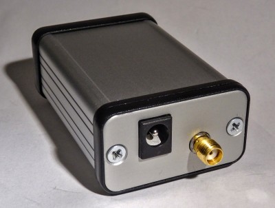
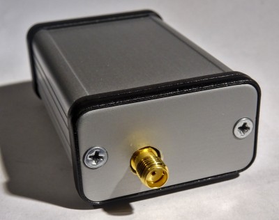
The PCB is designed for the four-layer JLCPCB RF process (stackup JLC7628), and neatly fits into a small Hammond 1455 case. A DC voltage between 7 and 15 volts can be used to supply the enclosed device, which makes it a convenient local oscillator source for the amateur laboratory.
While a four layer PCB would not have been strictly necessary, the SMA-to-GCPW transitions have been simulated using this SMA connector and PCB stackup. The thin (and somewhat well-defined) prepreg of the outer layers allows for proper impedance control and low dielectric losses.
The complete device can be built for below 100 € including the PCBs, which can be considered a nice low-cost alternative to a standalone generator for the 10 GHz range, especially when a 2.5 GHz generator is already available.
Images kindly provided by Sebastian, DL3YC.
Design Files
The design files are hosted here: https://git.loetlabor-jena.de/thasti/lofourx
This repository contains both schematics and layouts, as well as manufacturing data and measurements results.
Measurements
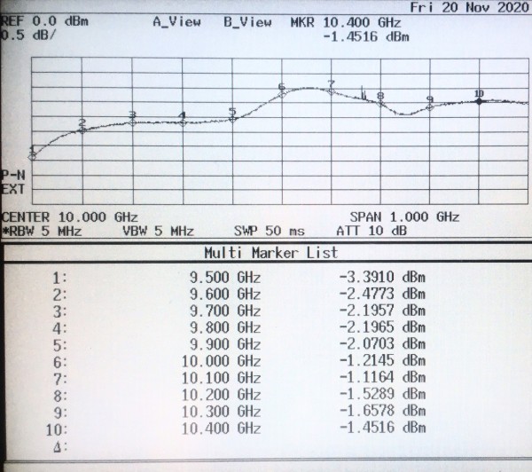
The PCB was built as designed and the PCB fitted with a 7 dB pad on its output. Cable and connector losses were minimized by directly connecting the PCB output to a spectrum analyzer input. A -10 dBm input signal was swept over the whole anticipated input range while the output power was measured. Output return loss in this configuration was not measured, but should be better than 20 dB, extrapolating from VNA measurements on the multiplier IC.
In this configuration, the output amplitude is about -2 dBm and varies only about +-1 dB over the whole frequency range. This is sufficient drive level for many applications in a lab. External attenuation can always be easily (and comparably cheaply) added by means of SMA inline attenuators.
Spectral content was verified at 10.368 GHz to be in line with the datasheet typical values:
- Fundamental: -60.5 dBc (2.592 GHz)
- 2nd harmonic: -26.3 dBc
- 3rd harmonic: -50.4 dBc
- 4th harmonic: 0 dBc (wanted output signal)
- 5th harmonic: -46.8 dBc
- 6th harmonic: -39.4 dBc


